Apr, 17, 2026
LED modules are used by connecting them to a compatible DC power supply at the correct voltage, mounting them to a heat-dissipating surface, and wiring them in series, parallel, or series-parallel configurations depending on the application requirements. The key rules are: always match the module's rated voltage, never exceed the maximum current, and always ensure adequate thermal management — heat is the primary cause of LED module failure and lumen depreciation. Following these fundamentals makes LED modules straightforward to integrate into virtually any lighting fixture or assembly.
Content
Before installation, read the module's datasheet to identify:
A constant-voltage LED driver (power supply) must provide the module's rated voltage with sufficient current capacity. Key selection rules:
LED modules generate heat at the chip junction — and junction temperature directly determines luminous efficiency, lumen output, and service life. At elevated junction temperatures, LEDs experience accelerated lumen depreciation: an LED module running at 85°C junction temperature may reach L70 (70% of initial lumens) in 30,000 hours, while the same module at 125°C junction temperature may reach L70 in fewer than 10,000 hours.
Effective thermal management requires:
Most 12V and 24V LED modules are wired in parallel — each module connects directly to the power supply rails. Parallel wiring allows individual module failure without affecting other modules in the circuit, and allows modules to be added or removed without redesigning the wiring. Maximum run lengths for parallel 12V LED modules are typically 5 meters before voltage drop becomes significant — use 24V systems for longer runs to minimize this effect.
High-power modules driven by constant-current drivers are typically wired in series — the same current flows through each module in the chain. This ensures uniform brightness across all modules but requires the driver voltage to be sufficient to supply the summed forward voltage of all series modules in the string.
| Application | Module Type | Key Installation Requirement |
|---|---|---|
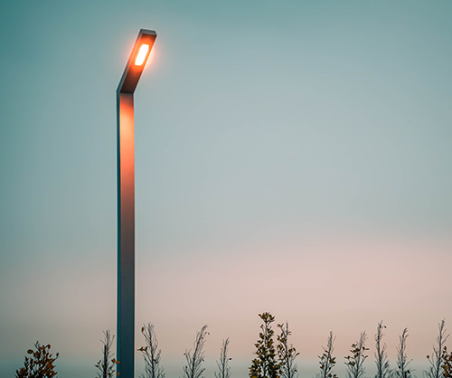
| Street light assembly / replacement | High-power COB or SMD array | Thermal paste to lamp body; IP66+ rated driver |
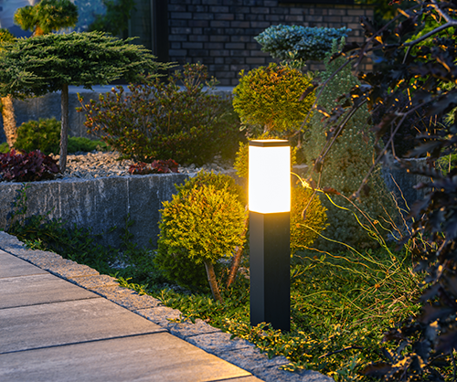
| Courtyard and garden light | SMD module, warm white | Waterproof connections; stable voltage supply |
| Advertising light box | Side-emitting or backlight modules | Even spacing; consistent CCT and CRI across modules |
| Wall light maintenance | Plug-in replacement module | Match original module power and CCT; verify driver compatibility |
| Decorative strip lighting | Flexible SMD strip module | Adhesive backing to aluminum channel; run length per voltage |
Related Products
 Private Industrial Park, Liangnong Town, Yuyao City, Ningbo City, Zhejiang Province, China
 +86-13486062091
 +86-574-2222 2345
 +86-574-2267 2345
 info@ym-lighting.com


 English
 中文简体
中文简体