Jul, 03, 2026
Installing a Light Pole is a structured multi-stage process that begins with site assessment and permits, proceeds through foundation excavation and concrete anchor bolt installation, continues with electrical conduit and wiring work, and concludes with pole erection, luminaire mounting, and final connection to the power supply. A properly installed light pole on a correctly sized concrete foundation in suitable soil will have a structural service life of 25 to 40 years with routine maintenance, while a pole installed without adequate foundation depth or anchor bolt specification may fail in moderate wind events within months.
The entire process from planning to energization typically takes 3 to 7 days for a single pole in normal soil conditions, including the mandatory concrete curing period of at least 72 hours before pole erection. For a row of 10 to 20 poles in a parking lot or roadway project, professional crews typically complete 4 to 8 poles per day once foundations are cured. Understanding each stage of the process -- and the technical specifications that govern each one -- is essential for anyone managing, supervising, or performing a light pole installation project.
Content
No light pole installation should begin without completing the planning and permitting stage. Skipping or rushing this stage is the most common cause of costly rework, project delays, and compliance failures.
Before any excavation begins, all underground utilities in the installation area must be located and marked. In the United States, this is accomplished by calling 811 (the national Call Before You Dig service) at least 3 business days before excavation. In the UK, the equivalent service is provided by LSBUD (Lines and Cables). Striking an unmarked underground power line during excavation is the leading cause of electrocution fatalities in construction work (source: OSHA Excavation Safety Statistics, 2022). Utility marking must be treated as a safety-critical prerequisite, not an administrative formality.
Utilities that must be located include electrical power lines, telecommunications cables, gas mains, water mains, sewer lines, and stormwater drainage. The marked safe excavation zone determines whether the planned pole location is viable or must be adjusted.
Most jurisdictions require one or more of the following permits for light pole installation on commercial, municipal, or roadway projects:
Permit requirements vary by jurisdiction and project scale. A single pole in a private parking lot may require only an electrical permit; a roadway lighting project with 50 poles will require structural engineering drawings, traffic control plans, and utility coordination submissions. Always confirm local requirements with the relevant authority having jurisdiction (AHJ) before proceeding.
The foundation design for a light pole is directly determined by the soil bearing capacity at the installation site. Standard light pole foundation tables assume a minimum soil bearing capacity of 1,500 to 2,000 pounds per square foot (psf) -- typical of compact sandy loam or clay. Sites with expansive clay, fill soil, organic material, or high water tables require geotechnical investigation and custom foundation design.
The structural engineer or pole manufacturer uses the following inputs to calculate the required foundation dimensions:
Most Light Pole manufacturers provide a foundation drawing with each pole order, specifying the anchor bolt circle diameter, bolt projection above the concrete surface, required concrete compressive strength (typically 3,000 to 4,000 psi at 28 days), and minimum foundation dimensions for standard soil conditions.
Before finalizing pole locations, a photometric analysis should be completed to confirm that the proposed pole spacing and mounting height will achieve the target illuminance levels. For parking lots, IESNA RP-20 recommends a minimum maintained average illuminance of 1.0 footcandle (fc) for basic security areas and 3.6 fc for high-activity commercial lots. For roadway lighting, ANSI/IES RP-8 provides illuminance and uniformity targets by road classification.
Photometric software (DIALux, AGi32, or equivalent) uses the luminaire's IES photometric file and the proposed pole layout to calculate point-by-point illuminance levels, average-to-minimum uniformity ratios, and light trespass at property boundaries. This analysis should be completed before ordering poles, as results may require adjustment of pole height, spacing, or luminaire selection.
Light pole selection is a technical decision that affects structural performance, installation method, maintenance access, and long-term cost. The primary selection parameters are pole height, material, base type, and wind load rating.
Mounting height is the most significant variable affecting both illuminance levels and the number of poles required. Higher mounting heights allow wider spacing but require more powerful luminaires and heavier structural poles. Common mounting heights by application are:
| Application | Typical Mounting Height | Typical Pole Spacing |
|---|---|---|
| Residential street lighting | 20 -- 25 ft (6 -- 8 m) | 80 -- 120 ft (25 -- 36 m) |
| Commercial parking lot | 25 -- 35 ft (8 -- 11 m) | 60 -- 100 ft (18 -- 30 m) |
| Arterial roadway | 30 -- 40 ft (9 -- 12 m) | 100 -- 150 ft (30 -- 45 m) |
| Sports field / athletic facility | 60 -- 80 ft (18 -- 24 m) | Layout-specific |
| Pathway and pedestrian area | 12 -- 18 ft (3.6 -- 5.5 m) | 40 -- 70 ft (12 -- 21 m) |
| Highway / freeway | 40 -- 50 ft (12 -- 15 m) | 150 -- 200 ft (45 -- 60 m) |
The three most common materials for light poles are steel, aluminum, and fiberglass composite. Each has distinct advantages depending on the installation environment and project requirements:
| Material | Typical Service Life | Best Applications | Key Considerations |
|---|---|---|---|
| Galvanized Steel | 25 -- 35 years | Roads, parking lots, sports facilities | High strength-to-weight, susceptible to rust if coating damaged |
| Aluminum | 30 -- 40 years | Coastal areas, decorative streetscapes | Corrosion resistant, lighter weight, higher cost than steel |
| Fiberglass (FRP) | 40 -- 50 years | High-corrosion environments, chemical plants, marine | Non-conductive, impact resistant, higher unit cost |
| Concrete / Spun Concrete | 40 -- 60 years | Highways, developing markets, high-vandalism areas | Very heavy -- requires crane for installation; lowest maintenance cost |
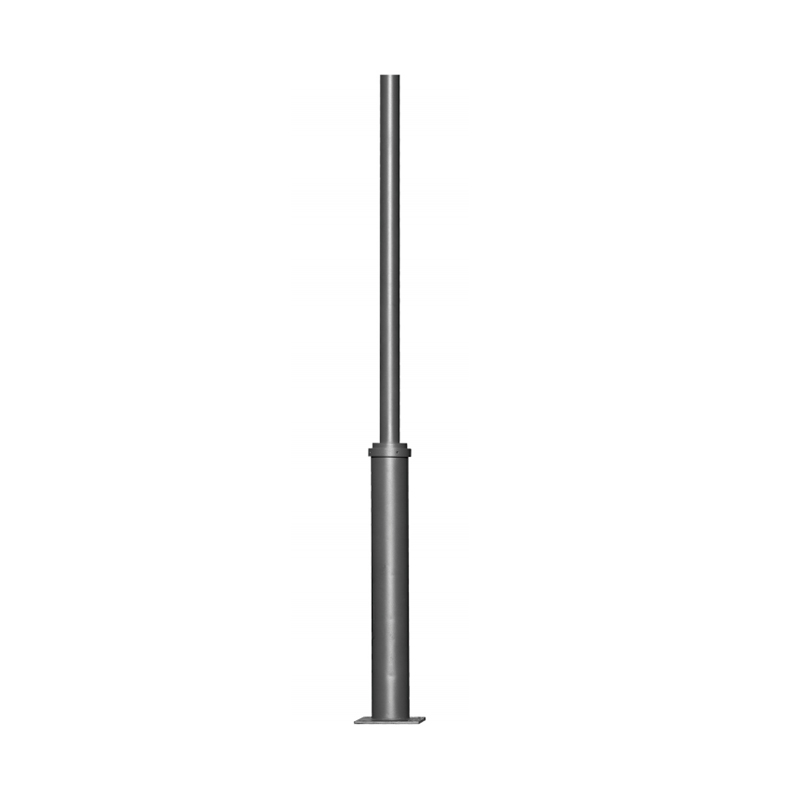
Direct burial poles are set directly into concrete in the ground, with no visible base hardware. They are cost-effective and structurally efficient for standard applications. The buried section depth is typically 10% of the pole height plus 2 feet -- so a 30-foot pole requires approximately 5 feet of embedment. Direct burial poles are common in roadway and parking lot applications where a clean appearance at grade level is preferred.
Anchor base poles sit on a concrete foundation and are secured with anchor bolts through a welded base plate at the bottom of the pole. This allows the pole to be removed and replaced without disturbing the foundation -- a significant advantage for high-impact locations where vehicle strike damage is possible. Anchor base installation also allows precise plumb adjustment during pole erection, which is more difficult with direct burial poles once the concrete has set.
The foundation is the most structurally critical element of the entire installation. A pole failure due to foundation inadequacy is almost always the result of one of three causes: insufficient embedment depth, undersized concrete volume, or inadequate concrete cure time before loading. All three are preventable with proper execution of this stage.
For direct burial poles, the hole must be excavated to the required embedment depth plus an additional 6 inches for a gravel drainage layer at the bottom. The hole diameter should be 3 to 4 times the pole base diameter to allow sufficient concrete cover on all sides -- a minimum of 6 inches of concrete between the pole surface and the soil wall.
For a standard 30-foot direct burial steel light pole with a 5-inch base diameter:
In soft or expansive soil conditions, the foundation engineer may specify a larger diameter or additional depth. Never reduce embedment depth to save excavation time -- this is the single most common cause of preventable pole failures in moderate wind events.
For anchor base poles, the foundation is a reinforced concrete pier sized to the pole manufacturer's foundation drawing. A typical anchor bolt foundation for a 30-foot commercial light pole measures approximately 18 to 24 inches in diameter and 4 to 5 feet deep, with four anchor bolts set in an L-shaped configuration to resist both uplift and lateral wind load.
The anchor bolt installation process requires particular attention to accuracy:
Concrete that freezes before achieving adequate strength will be permanently weakened. When ambient temperatures are below 40 degrees F (4 degrees C), the following measures are required:
The electrical infrastructure supporting the light pole must be installed before or concurrently with the foundation work, as the conduit stub-up must pass through the foundation concrete. This stage covers the underground conduit run, wire pulling, and termination at the pole base.
The National Electrical Code (NEC) Article 300.5 specifies minimum burial depths for electrical conductors and conduit in the United States. The applicable depth depends on conduit type and circuit voltage:
| Wiring Method | Minimum Burial Depth (NEC 300.5) | Notes |
|---|---|---|
| Rigid Metal Conduit (RMC / IMC) | 6 inches | Shallowest option; highest mechanical protection |
| PVC Schedule 40 / Schedule 80 | 18 inches | Most common for light pole circuits; cost-effective |
| Direct-buried UF cable (no conduit) | 24 inches | Least preferred; no mechanical protection or future wire pull access |
| Under roads / driveways (any method) | 24 inches minimum | Additional depth for vehicle load protection |
For most commercial and municipal light pole projects, PVC Schedule 40 conduit at 24 inches depth is the standard specification -- deep enough to protect against accidental damage during landscaping or future minor excavation, while remaining cost-effective for long runs.
Wire size is determined by the luminaire load in watts, the circuit voltage, the number of poles on the circuit, and the maximum permissible voltage drop from the power source to the last pole. The NEC limits voltage drop to 3% for branch circuits and 5% for the combined feeder and branch circuit. Excessive voltage drop reduces luminaire light output and can damage LED drivers.
As an example: a circuit supplying 10 LED luminaires at 150 watts each (1,500 watts total at 120V = 12.5 amps) over a 300-foot run requires a minimum of No. 10 AWG copper wire to hold voltage drop below 3%. The same circuit at 240V requires only No. 12 AWG, which is why many commercial light pole circuits are wired at 240V or 277V to reduce wire size and cost on long runs.
Each light pole should have a hand hole opening in the pole shaft -- typically a rectangular opening approximately 4 inches x 6 inches located 18 to 24 inches above grade -- providing access to the wire connections, fuse, and photocontrol receptacle inside the pole. The hand hole cover is secured with a vandal-resistant screw. Wire terminations inside the pole must be made with weatherproof wire connectors rated for wet locations, as condensation inside the pole shaft is common.
Pole erection is the most physically hazardous stage of the installation process. Falling poles and loads, overhead power line contact, and working at height are the primary risks. Proper equipment selection, crew briefing, and adherence to lift plan procedures are non-negotiable.
The equipment required depends on pole height, weight, and site access:
Direct burial pole installation differs from anchor base in one critical aspect: once the concrete is poured with the pole in place, the position is permanent. Plumbing must therefore be checked and corrected during the pour, before the concrete sets.
With the pole erected and concrete cured, the luminaire and any tenon or arm mount can be installed. This stage is typically performed from an aerial lift (bucket truck) or by assembling the luminaire and arm at ground level and lifting the assembly onto the pole top during erection -- a method preferred when the luminaire is large or the pole has a slip-fit tenon top.
Tenon-mount luminaires slip over a round tenon tube welded or threaded to the top of the pole, and are secured with stainless steel set screws. The tenon diameter is standardized at 2-3/8 inch OD for most North American street and area lighting. Tenon mount is the fastest and simplest attachment method -- installation typically takes less than 5 minutes per luminaire.
Arm-mount configurations use a welded or slip-fit bracket arm extending horizontally from the pole shaft, positioning the luminaire away from the pole centerline. This is used when the lighting target area is offset from the pole location, or when multiple luminaires must be mounted at different azimuths on a single pole. Arm-to-pole connections are secured with through-bolts or set screws through the pole shaft wall.
The supply wires run from the hand hole up through the pole interior and exit at the top through the tenon or arm wire chase. Connections at the luminaire must be made with weatherproof connectors rated for wet locations -- typically lever-type or twist-on connectors rated for direct burial or wet locations. All connections inside the luminaire must be accessible for maintenance without removing the entire fixture from the pole.
For LED luminaires with integral drivers, confirm that the supply voltage matches the driver input voltage rating before energizing. Most commercial LED area lights accept a wide input voltage range of 120 to 277V AC, but this must be verified against the specific model's specification sheet. Mismatched voltage is a leading cause of premature LED driver failure.
Most commercial street and area light poles are equipped with a NEMA 7-pin photocontrol twist-lock receptacle at the top of the pole or on the luminaire, accepting a photocontrol that switches the luminaire on at dusk and off at dawn. For projects with dimming or networked control requirements, a 0-10V dimming control wire must be run from the control system through the conduit network to each pole, in addition to the power supply conductors.
The final stage before the installation is complete is the electrical connection to the power source, followed by a systematic testing and commissioning process.
Light pole circuits are typically fed from a dedicated lighting panel or photocell-switched branch circuit in an existing distribution panel. The circuit must be protected by an appropriately rated breaker -- calculated as 125% of the continuous load per NEC Article 210.20. For a circuit supplying 10 LED luminaires at 150W each (total 1,500W at 120V = 12.5A), the minimum breaker size is 12.5 x 1.25 = 15.6A, rounded up to a 20A breaker.
All wiring must be inspected and approved by the AHJ (Authority Having Jurisdiction) before the circuit is energized. The electrical inspector will verify conduit installation, burial depth, wire sizing, connection quality, grounding, and panel labeling.
Each metal light pole must be bonded to the equipment grounding conductor (EGC) running through the supply conduit. This grounding is critical for personnel safety -- it ensures that if the supply wire inside the pole develops an insulation fault and energizes the pole shaft, the fault current will trip the circuit breaker rather than energizing the pole to dangerous touch voltage. Grounding continuity must be verified with a low-resistance ohmmeter (less than 1 ohm) from the pole base to the panel ground bus before energizing the circuit.
In areas with high lightning exposure, a separate lightning protection ground rod (minimum 8-foot copper-clad steel) driven adjacent to the pole foundation and bonded to the pole base plate provides additional protection against lightning-induced transients in the lighting circuit.
Before signing off on the completed installation, perform the following commissioning checks:
Document the completed installation with photographs of each pole foundation, anchor bolt connections, wire terminations, and the energized luminaires at night. This documentation is valuable for future maintenance reference and for resolving any warranty or insurance claims.
The following errors account for the majority of light pole installation failures, warranty claims, and safety incidents. Each is preventable with attention to specification and procedure:
| Common Mistake | Consequence | Prevention |
|---|---|---|
| Insufficient concrete cure time before erection | Foundation failure in first wind event; pole lean or topple | Wait minimum 72 hours at normal temps; 5 to 7 days in cold weather |
| Anchor bolts misaligned or misplaced | Pole base plate does not fit; foundation must be demolished and rebuilt | Use rigid template; verify bolt positions before and immediately after pour |
| Embedment depth too shallow (direct burial) | Pole overturn in moderate wind; structural failure | Follow manufacturer's embedment table; never reduce depth for convenience |
| No conduit stub-up through foundation | Wire must be routed externally or foundation broken to add conduit | Install conduit before pouring; verify before concrete placement |
| Anchor bolts not torqued to specification | Base plate loosens under cyclic wind load; fatigue cracking at weld | Use calibrated torque wrench; install lock washers or double nuts |
| Pole not grounded | Electrocution hazard if wiring fault occurs inside pole shaft | Verify grounding continuity with ohmmeter before energizing |
| Incorrect supply voltage to LED luminaire | Driver failure within weeks; luminaire warranty voided | Verify luminaire input voltage against supply voltage before connection |
| Wire undersized for circuit length | Excessive voltage drop; reduced light output; driver overheating | Calculate voltage drop before wire selection; include all poles in calculation |
A properly installed Light Pole requires periodic maintenance to achieve its full design service life. The following maintenance schedule reflects industry best practice for commercial and municipal light pole installations (source: AASHTO Roadway Lighting Design Guide, 2018):
| Maintenance Task | Frequency | Notes |
|---|---|---|
| Visual pole inspection for corrosion, damage, lean | Annual | Inspect at pole base, hand hole, and arm-to-pole connection |
| Anchor bolt torque check | Every 2 to 3 years | Retorque to specification if any looseness detected |
| Coating and paint touch-up | As needed; typically 5 to 10 years | Address any chips or rust spots immediately to prevent corrosion propagation |
| Luminaire cleaning | Every 2 to 3 years | Clean lens and optical surfaces to restore light output |
| Wire and connection inspection | Every 5 years | Check for insulation degradation, loose connections, corrosion at terminals |
| Structural inspection (at-grade corrosion probe) | Every 5 to 10 years for steel poles in aggressive environments | Use ultrasonic thickness gauge to check wall thickness at grade line |
Steel light poles in coastal areas, northern road salting zones, or industrial environments are particularly susceptible to at-grade corrosion -- the zone just above and below the soil surface where moisture, oxygen, and salt or chemical exposure are concentrated. Wall thickness loss of more than 25% at any point on the pole shaft is typically the threshold for pole replacement under AASHTO structural standards.
Related Products
 Private Industrial Park, Liangnong Town, Yuyao City, Ningbo City, Zhejiang Province, China
 +86-13486062091
 +86-574-2222 2345
 +86-574-2267 2345
 info@ym-lighting.com


 English
 中文简体
中文简体


 Hot-dip Galvanized Pole Light customized Outdoor Use For Post Top Lights")


